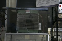
Spark Chamber
Optional apparatus: external scintillator/PMT unit with power supplies, discriminator and logic unit.
Description:
| Operation: 0) Ensure the spark chamber setup is located in a well ventilated area. 1) Connect balloon grade Helium to spark chamber hose, remove hose clamp. 2) Set Helium gas to 2PSI, open gas valve fully: gas flow will be visible as vigorous bubbling in the oil column on the side of the spark chamber within 2 minutes. 3) Purge spark chamber with Helium for several hours 4) Ensure chamber HV and PMT power are off 5) Ensure all connectors are secure 6) Turn on spark chamber AC 7) Turn on PMT power (3kV, see marking on dial) 8) wait for thyratron mesh current to reach ____mA 9) Turn on Chamber HV (push button) 10) Gradually increase chamber HV to 8kV (DO NOT EXCEED 10kV). 11) Observe sparks Shutdown: 1) Ramp down Chamber HV 2) Turn off PMT power 3) Turn off AC 4) Turn off Helium 5) Re-attach gas clamp on hose, disconnect Helium line. CAUTION: LARGE POTENTIALS MAY EXIST IN THE UNIT EVEN AFTER HV HAS BEEN TURNED OFF. ENSURE INTERNAL CAPACITORS HAVE DISSIPATED PRIOR TO WORKING ON UNIT. Finetuning the Spark Chamber: The built-in Scintillator/PMT/coincidence circuit has additional but limited adjustments. The information here is for reference only: (some of these require taking the unit out of its housing) A) PMT power supply has individual potentiometers in the back of the unit (beside the PMT power plugs) to adjust the voltage levels. B) Screen Grid current in the front of the unit is a bias adjustment for the Thyratron. C) Inside the electronic unit to the spark chamber, where the PMT signal inputs are connected, is a smaller box housing the discriminator and coincidence circuit. Each channel (2) has its own potentiometer to adjust signal threshold levels. Even with these adjustments the built-in system appears to be noisy (i.e. prone to random discharge). External units have been successfully used to improve this. Additional Equipment needed are: 2 Scintillator/PMT units Rack with the following attached: PMT Power supplies, Discriminator unit, Logic unit Operation: a) Ensure the spark chamber setup is located in a well ventilated area. b) Connect balloon grade Helium to spark chamber hose, remove hose clamp. c) Set Helium gas to 2PSI, open gas valve fully: gas flow will be visible as vigorous bubbling in the oil column on the side of the spark chamber within 2 minutes. d) Purge spark chamber with Helium for several hours e) Ensure chamber HV and PMT power are off f) Connect scintillator/PMT units to external power supply g) Connect scintillator/PMT signals to 2 inputs on Discriminator unit. h) Set PMT power supply to -2kV (*************DOUBLE CHECK THE NEGATIVE******************) i) Adjust discriminator threshold. j) Connect discriminator outputs to AND inputs in the logic unit. k) Connect logic unit output to counter, check counts. l) Disconnect built-in scintillators & PMTs from the back of the spark chamber electronics unit (2 signal & 2 power). m) Connect logic unit output to both signal inputs on the back of the spark chamber electronics unit. n) Turn on AC to the spark chamber. o) wait for thyratron mesh current to reach ____mA p) Turn on Chamber HV (push button) q) Gradually increase chamber HV to 8kV (DO NOT EXCEED 10kV). r) Observe sparks |


