|
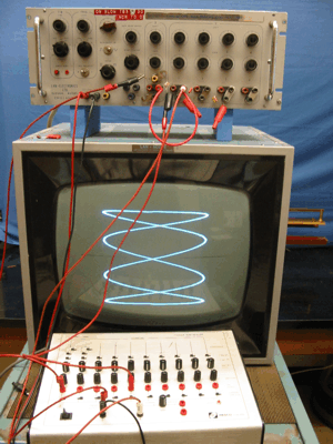
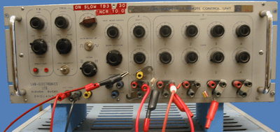
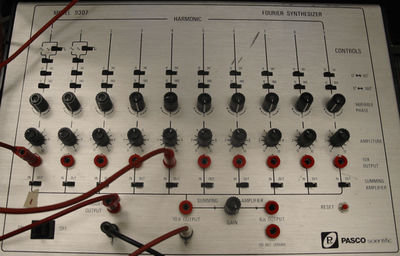
Setup:
1. Connect the trigger output from Pasco Scientific to Ext. trigger on Lan Scope.
2. Connect the ground output from Pasco Scientific to Ext. Ground on Lan Scope.
3. Connect channel 1 output from Pasco Scientific to 0.01 micro farad capacitor connected to positive channel Y1.
4. Connect channel 2 output from Pasco Scientific to 0.01 micro farad capacitor connected to positive channel X1.
5. Connect main ground from Pasco Scientific to Y1 negative.
6. On Lan Scope jumper X ground to Y1 ground.
7. Adjust the frequencies of the Pasco generator so that the gains and phases are approx. equal.
8. Adjust the C.R.O. gain control so that a round circle is formed.
Method:
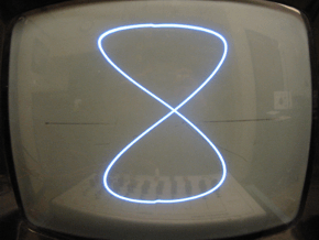
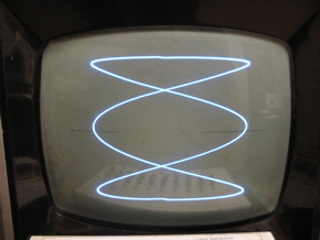
1. Set X and Y to the same frequency (Channel #1a and #1a)
2. Observe the circular pattern produced by two waves of the same frequency
3. Keeping the Y input fixed at 1(a) move the x input to different frequency multiples.
4. Observe the change in the Lissajous figures
|

")
")